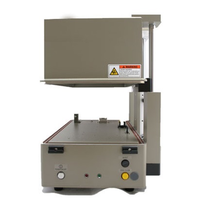
Description
The TC-5901B Pneumatic RF Shield Box is designed for high-volume wireless production environments that require consistent and repeatable RF isolation. This automated shielding enclosure uses a pneumatic lid mechanism to ensure uniform compression and dependable signal containment during every test cycle.
The TC-5901B RF Shield Box isolates devices under test from ambient interference, allowing engineers to validate Wi-Fi, Bluetooth, cellular, and IoT products in a controlled environment.
Pneumatic RF Shielded Enclosure for Production Efficiency
This pneumatic RF shielded enclosure increases throughput while reducing operator fatigue. The air-driven open-and-close system delivers consistent sealing pressure, which improves isolation performance and minimizes signal leakage.
Manufacturers integrate this enclosure into automated fixtures, robotic systems, and validation labs. Custom I/O panels support RF connectors, USB filters, Ethernet feedthroughs, and filtered power connections.
Explore related solutions:
RF Shield Box Systems: https://ctscorp-usa.com/rf-shield-boxes/
RF Feedthrough Filters: https://ctscorp-usa.com/rf-feedthrough-filters/
Reliable RF Isolation for Compliance Testing
Accurate RF validation requires strong shielding performance. Enclosures like the TC-5901B RF Shield Box support testing aligned with industry standards, including:
Federal Communications Commission (FCC): https://www.fcc.gov
IEEE Wireless Standards: https://standards.ieee.org
By minimizing external interference, manufacturers reduce retesting and maintain compliance during certification processes.
Specifications
- RF Shield Effectiveness: >80dB, DC ~ 2.5GHz
- RF Connectors: 2 Type-N (external), 2 SMA (internal)
- Data Connectors:
- 2 DB9(p) outside and DB9(s) inside, 1000pF Pi filter
- DB25(p) outside and DB25(s) inside, 1000pF Pi filter
- DB9(p) outside and DB9(s) inside, for LAN or USB 1.1, 100pF Pi filter
- Data Line Capacity: 100 VDC, 3A Max
- Remote Control: RS232, 3 Wire, 9 pin D Type connector
- Compressed Air Requirement: 5 to 10 Bar
- Compressed Airline Connector: Sang-A PMM06, 6 mm OD hose, one-touch push-on fitting
- Air Connector Between fixture and main body: 4 mm push on fitting
- Line Voltage: Universal 100 to 240 VAC, 50/60 Hz, 16 watt
- Working Space: 408(W) x 218(D) x 135(H) mm
- Dimensions: 459(W) x 300(D) x 302(H) mm, Lid Closed. 449(H) mm, Lid Open
- Weight without Accessories: 20 kg
- Accessories supplied:
- 4003-0001, DB9(s) to DB9(s) RS-232C Cable, 2m, 1pc.
- 4003-0004, DB9(p) to DB9(s) Cable, 1m, 2pcs
- 4003-0005, DB25(p) to DB25(s) Cable, 1m, 1pc.
- 4006-0004, N(m) to N(m) Cable, 1m, 1pc.
- 4008-0008, RJ45 to DB9(p) Cable, 30cm, 1pc.
- 4008-0009, RJ45 to DB9(s) Cable, 1.5m, 1pc.
- 4009-0006, HDEB9(s) to USB A(p) Cable, 1m, 1pc.
- 4009-0007, HDEB9(p) to USB A(s) Cable, 15Cm, 1pc.
- Power Cord, 1pc., Hand Valve, 1pc.
- Safety Shield, 1pc., Lid Stopper, 1pc.
Lid Characteristics
- Long Life Up-Down design
- Lid Speed Control Valve
- Dual Pressure: Lid closes without air pressure
- Lid Down Sensor: Lid opens if the lid doesn’t close fully within 2 sec.
- Initial Lid Position: Lid opens when the air is connected regardless of AC power
- Internal Electronic Cycle Counter (downloadable to PC thru RS-232C)
Electrical I/O
- User Data I/O Connectors
- 2 DB9(p) outside and DB9(s) inside, 1000pF Pi filter
- DB25(p) outside and DB25(s) inside, 1000pF Pi filter
- DB9(p) outside and DB9(s) inside, for LAN or USB 1.1, 100pF Pi filter
- RF Connectors: N(f) outside and SMA(f) inside
- Remote Control Connector: RS-232C : DB9(p), 3wire
- AC Line Input: IEC Type, Detachable
***Isolation example above is based on I/O configuration as specified above. Isolation may be higher or lower based on specific I/O configuration installed.
Custom Configurations
TC Manual RF Shield Box Custom I/O Interface Panel
Customized I/O Interface panels are available. Please contact the CTS sales team for more information
| I/O Interface | Order Number | Typical Data Rate/Line Voltage | Typical Shielding* |
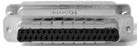
DB37, 1000pF pi Filter | 3409-0012-1 | 3 Mbps / 100 VDC,
5 Amps max | >70 dB from 0.5 to 2 GHz
>80 dB from 2 to 3 GHz
>70 dB from 3 to 6 GHz |
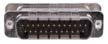
DB25, 1000pF pi Filter | 3409-0009-1 | 3 Mbps / 100 VDC,
5 Amps max | >70 dB from 0.5 to 2 GHz
>80 dB from 2 to 3 GHz
>70 dB from 3 to 6 GHz |
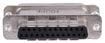
DB25, 100pF pi Filter | 3409-0014-1 | 10 Mbps / 100 VDC,
5 Amps max | >50 dB from 0.5 to 2 GHz
>60 dB from 2 to 3 GHz
>60 dB from 3 to 6 GHz |
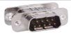
DB9, 1000pF pi Filter | 3409-0008-1 | 3 Mbps / 100 VDC,
5 Amps max | >70 dB from 0.5 to 2 GHz
>80 dB from 2 to 3 GHz
>70 dB from 3 to 6 GHz |
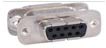
DB9, 100pF pi Filter | 3409-0010-1 | 10 Mbps / 100 VDC,
5 Amps max | >50 dB from 0.5 to 2 GHz
>60 dB from 2 to 3 GHz
>60 dB from 3 to 6 GHz |
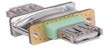
USB 2.0 Filter | 3409-0018A-3 | 480 Mbps / 5 V, 500 mA /
Max Current: 5A | >60 dB from 0.5 to 2 GHz
>70 dB from 2 to 3 GHz
>70 dB from 3 to 6 GHz |
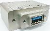
USB 3.0 Filter(Active) | 3409-0042A-1 | 5000 Mbps / 5 V, 900 mA /
Max Current: 1.5 A | >70 dB from 0.5 to 2 GHz
>70 dB from 2 to 3 GHz
>55 dB from 3 to 6 GHz |
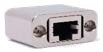
RJ-45 Filter | 3409-0022A | 1 Gbit/s Copper-Line
Ethernet (1000 BASE-T) | >60 dB from 0.5 to 2 GHz
>70 dB from 2 to 3 GHz
>70 dB from 3 to 6 GHz |
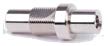
DC Power Adaptor | 3406-0004A | 50 VDC,
3 Amps max | >70 dB from 0.5 to 2 GHz
>80 dB from 2 to 3 GHz
>80 dB from 3 to 6 GHz |
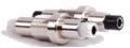
DC Power Adaptor,
Banana Jack Type | 3406-0005A
3406-0006A | 50 VDC,
10 Amps max | >70 dB from 0.5 to 2 GHz
>80 dB from 2 to 3 GHz
>80 dB from 3 to 6 GHz |

AC Power Adaptor | 3103-0009A | 250 VAC,
7 Amps max | >70 dB from 0.5 to 2 GHz
>80 dB from 2 to 3 GHz
>80 dB from 3 to 6 GHz |
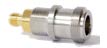
RF, N-SMA Connector | 3408-0038 | | >60 dB from 0.5 to 2 GHz
>70 dB from 2 to 3 GHz
>70 dB from 3 to 6 GHz |

RF, SMA-SMA Connector | 3408-0039 | | >60 dB from 0.5 to 2 GHz
>70 dB from 2 to 3 GHz
>70 dB from 3 to 6 GHz |
*SPECIFICATIONS SUBJECT TO CHANGE WITHOUT PRIOR NOTICE
- Each shielding effectiveness is measured when each I/O interface panel, which is shown above, is mounted.
- Above data was measured by Tescom, The Shielding Effectiveness might be different based on the measuring method and condition.
- This data has been measured under the condition that the cables are not connected to each filters. When the cables are connected it can affect the shielding performance.