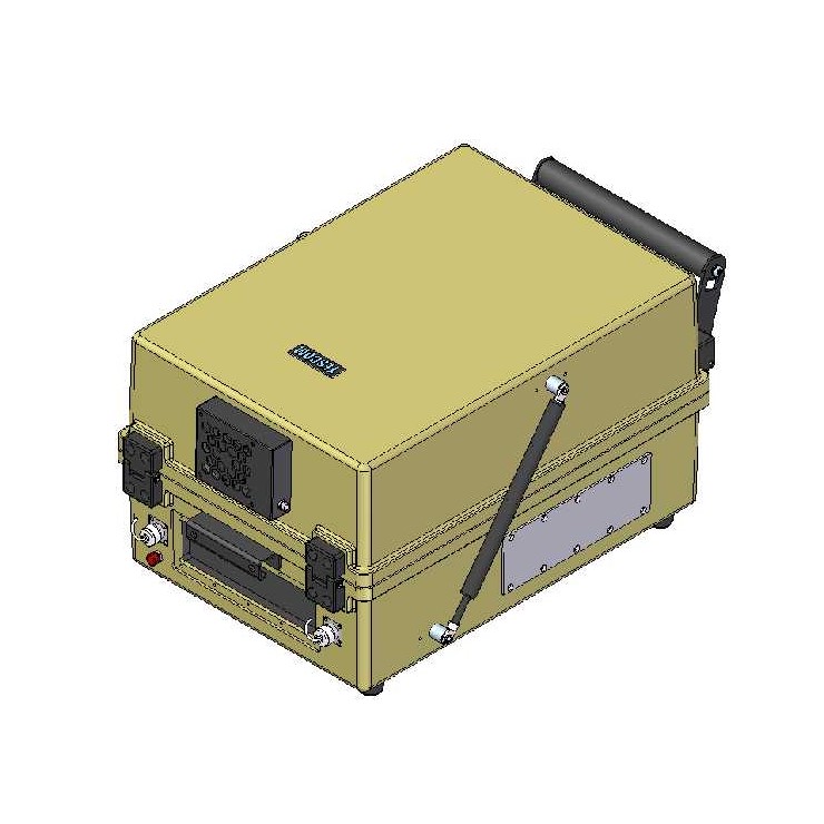
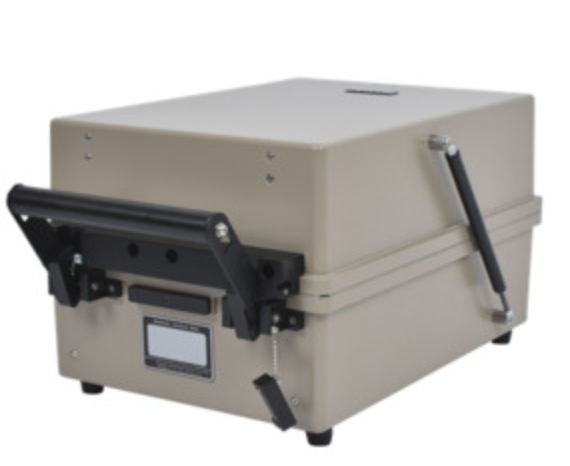
Description
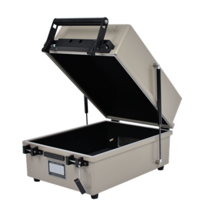
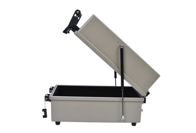
The TC5922BU-01 RF Shield Box fits easily on a desktop or benchtop while using minimal space. At the same time, it provides enough room for small to medium-size devices. Its ergonomic design supports frequent opening and closing during daily test cycles. It also simplifies routine maintenance.
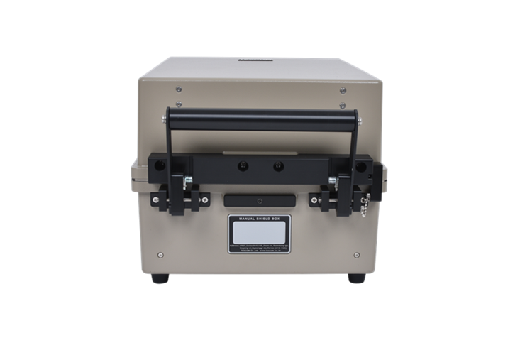
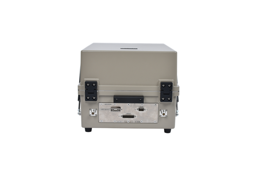
Engineers can customize the rear and side I/O plates to match changing test requirements. These plates are field-replaceable, so teams avoid downtime and shipping delays. Instead of sending the RF shield box back for modifications, you can update the configuration on site. This flexibility helps keep testing on schedule.
In today’s fast-paced development cycles, time matters. Faster testing moves products from design to production more efficiently. Ultimately, reducing delays gives your team a competitive advantage.
For over-the-air testing, pair the RF Faraday cage with one of our antenna couplers. Install the coupler in a universal grid test fixture for best results. This setup delivers reliable and repeatable OTA measurements.
Typical RF Shielding
TC-5922BU-01 Shield Box Typical RF Shielding
The shielding effectiveness below is measured when the blank panel is mounted; other I/O interface panel results a different shielding effectiveness of the shield box.
| Frequency |
Shielding effectiveness (dB) |
| .1 to 3 GHz |
> 70 dB |
| 3 GHz to 6 GHz |
> 60 dB |
| 6 GHz to 12 GHz |
> 60 dB |
- Each shielding effectiveness is measured when each I/O interface panel, which is shown above, is mounted.
- Above data was measured by Tescom, The Shielding Effectiveness might be different based on the measuring method and condition.
- This data has been measured under the condition that the cables are not connected to each filters. When the cables are connected it can affect the shielding performance.
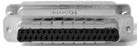
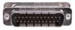
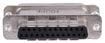
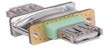
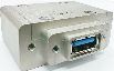
Custom Configurations
TC Manual RF Shield Box Custom I/O Interface Panel
Customized I/O Interface panels are available. Please contact the CTS sales team for more information
| I/O Interface | Order Number | Typical Data Rate/Line Voltage | Typical Shielding* |
DB37, 1000pF pi Filter | 3409-0012-1 | 3 Mbps / 100 VDC,
5 Amps max | >70 dB from 0.5 to 2 GHz
>80 dB from 2 to 3 GHz
>70 dB from 3 to 6 GHz |
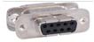
DB25, 1000pF pi Filter | 3409-0009-1 | 3 Mbps / 100 VDC,
5 Amps max | >70 dB from 0.5 to 2 GHz
>80 dB from 2 to 3 GHz
>70 dB from 3 to 6 GHz |
DB25, 100pF pi Filter | 3409-0014-1 | 10 Mbps / 100 VDC,
5 Amps max | >50 dB from 0.5 to 2 GHz
>60 dB from 2 to 3 GHz
>60 dB from 3 to 6 GHz |
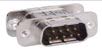
DB9, 1000pF pi Filter | 3409-0008-1 | 3 Mbps / 100 VDC,
5 Amps max | >70 dB from 0.5 to 2 GHz
>80 dB from 2 to 3 GHz
>70 dB from 3 to 6 GHz |
DB9, 100pF pi Filter | 3409-0010-1 | 10 Mbps / 100 VDC,
5 Amps max | >50 dB from 0.5 to 2 GHz
>60 dB from 2 to 3 GHz
>60 dB from 3 to 6 GHz |
USB 2.0 Filter | 3409-0018A-3 | 480 Mbps / 5 V, 500 mA /
Max Current: 5A | >60 dB from 0.5 to 2 GHz
>70 dB from 2 to 3 GHz
>70 dB from 3 to 6 GHz |
USB 3.0 Filter(Active) | 3409-0042A-1 | 5000 Mbps / 5 V, 900 mA /
Max Current: 1.5 A | >70 dB from 0.5 to 2 GHz
>70 dB from 2 to 3 GHz
>55 dB from 3 to 6 GHz |
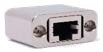
RJ-45 Filter | 3409-0022A | 1 Gbit/s Copper-Line
Ethernet (1000 BASE-T) | >60 dB from 0.5 to 2 GHz
>70 dB from 2 to 3 GHz
>70 dB from 3 to 6 GHz |
DC Power Adaptor | 3406-0004A | 50 VDC,
3 Amps max | >70 dB from 0.5 to 2 GHz
>80 dB from 2 to 3 GHz
>80 dB from 3 to 6 GHz |
DC Power Adaptor,
Banana Jack Type | 3406-0005A
3406-0006A | 50 VDC,
10 Amps max | >70 dB from 0.5 to 2 GHz
>80 dB from 2 to 3 GHz
>80 dB from 3 to 6 GHz |

AC Power Adaptor | 3103-0009A | 250 VAC,
7 Amps max | >70 dB from 0.5 to 2 GHz
>80 dB from 2 to 3 GHz
>80 dB from 3 to 6 GHz |
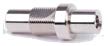
RF, N-SMA Connector | 3408-0038 | | >60 dB from 0.5 to 2 GHz
>70 dB from 2 to 3 GHz
>70 dB from 3 to 6 GHz |

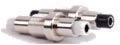
RF, SMA-SMA Connector | 3408-0039 | | >60 dB from 0.5 to 2 GHz
>70 dB from 2 to 3 GHz
>70 dB from 3 to 6 GHz |
*SPECIFICATIONS SUBJECT TO CHANGE WITHOUT PRIOR NOTICE
- Each shielding effectiveness is measured when each I/O interface panel, which is shown above, is mounted.
- Above data was measured by Tescom, The Shielding Effectiveness might be different based on the measuring method and condition.
- This data has been measured under the condition that the cables are not connected to each filters. When the cables are connected it can affect the shielding performance.