Description
The STE3800 RF Shield Box is designed to deliver reliable RF isolation for testing wireless devices in both laboratory and production environments. This enclosure creates a controlled RF space that blocks external interference and prevents unwanted signal leakage during critical test operations.
Engineers use the STE3800 RF Shield Box to evaluate RF-enabled products such as PCBs, wireless modules, and fully assembled devices. By isolating the device under test from ambient RF signals, the enclosure helps ensure consistent and repeatable measurement results across common wireless technologies.
RF Shield Box for Lab and Manufacturing Use
This RF shield box supports both development and manufacturing workflows. Its durable construction provides dependable shielding performance while maintaining proper airflow and thermal stability. As a result, devices can operate within published specifications during extended test cycles without compromising performance or reliability.
Flexible Configuration and Integration Options
The enclosure supports a range of configuration options to meet different testing requirements. Available options include RF connectors, filtered I/O interfaces, and automation-ready features. Because of this flexibility, the RF shield box adapts easily to evolving test setups in both lab and production environments.
Reliable Performance for Everyday RF Testing
Designed for long-term use, the enclosure balances RF isolation, usability, and thermal performance. This balance improves test efficiency and helps maintain stable workflows across multiple test stations and environments.
Typical Applications
-
Wireless device development and validation
-
RF performance and pre-compliance testing
-
Manufacturing and production testing
-
Lab environments requiring repeatable RF isolation
Overall, the STE3800 RF Shield Box provides a dependable solution for teams that require accurate RF measurements, consistent isolation, and efficient wireless testing workflows.
IO Configurations
Custom Configuration Options
- RF FEEDTHROUGH: BNC, TNC, SMA, SMB, UHF, Type-N
- FIBER OPTIC: Fiber optic bulkhead feedthrough, ST, FC
- DUST COVERS: Dust cover capes with security chains available for all RF feedthrough connectors
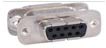
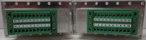
- RF FILTERED DATA: DB9 (10pF), DB9 (100pF), DB9 (1000pF), DB15 (100pF), DB15 (1000pF), DB25 (310pF), DB25 (1000pF), DB37 (310pF), DB37 (1000pF), RJ45/DB9 Filtered, RJ11/DB9 Filtered, USB1/DB9 Filtered
- POWER CONNECTIONS: 4-Pole filtered barrier strip feed through, 6-Pole filtered barrier strip feed through, internal surge protected power strips (110VAC, 220VAC International)
- VENTILATION OPTIONS: Dual side mounted RF filtered vents with single filtered exhaust muffin fan, passive vent only
- RF ABSORBENT FOAM: Standard 1/2″ thick RF absorbent foram liner provides 24dB attenuation. 3/4″ thick foam is standard on the STE3800 and available as an option to provide a flatter response
- FIBER TRANSCEIVER: Icron Technologies USB 2.0 Fiber Transceiver System available for devices up to 480 MB/s
Note: RF Isolation specs are measured at 1M with terminated RF feedthrough coaxial connectors installed. Actual isolation & attenuation can be affected by adding additional filtered and non-filtered connectors. Check with us for specific connector specifications. STE series I/O interfaces, connectors, and options are frequently updated. Check with us for updates.
| I/O Interface | Order Number | Typical Data Rate/Line Voltage | Typical Shielding* |
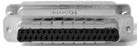
DB37, 1000pF pi Filter | 3409-0012-1 | 3 Mbps / 100 VDC,
5 Amps max | >70 dB from 0.5 to 2 GHz
>80 dB from 2 to 3 GHz
>70 dB from 3 to 6 GHz |
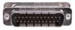
DB25, 1000pF pi Filter | 3409-0009-1 | 3 Mbps / 100 VDC,
5 Amps max | >70 dB from 0.5 to 2 GHz
>80 dB from 2 to 3 GHz
>70 dB from 3 to 6 GHz |
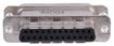
DB25, 100pF pi Filter | 3409-0014-1 | 10 Mbps / 100 VDC,
5 Amps max | >50 dB from 0.5 to 2 GHz
>60 dB from 2 to 3 GHz
>60 dB from 3 to 6 GHz |
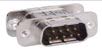
DB9, 1000pF pi Filter | 3409-0008-1 | 3 Mbps / 100 VDC,
5 Amps max | >70 dB from 0.5 to 2 GHz
>80 dB from 2 to 3 GHz
>70 dB from 3 to 6 GHz |
DB9, 100pF pi Filter | 3409-0010-1 | 10 Mbps / 100 VDC,
5 Amps max | >50 dB from 0.5 to 2 GHz
>60 dB from 2 to 3 GHz
>60 dB from 3 to 6 GHz |
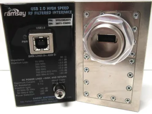 | STEUSB2071 |
Max Current: 2A | >80 dB from 741MHz to 6 GHz |
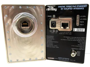 | STEETHD10G | 10 Gbps | >80dB 100MHz to 40GHz |
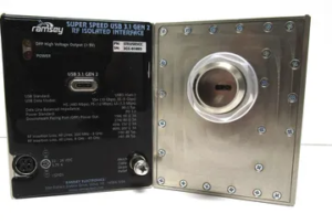 | STEUSB3CC | Max Current 3.75A | >90 DB 200MHz to 8 GHz |
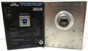 | STEUSB312 | Max Current: 2A | >90 DB 200MHz to 8 GHz |
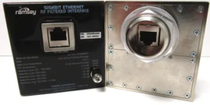 | STEGBE4591 | 1 GBps | >90 DB 700MHz to 8 GHz |
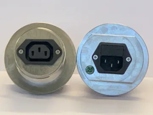 | IEC25010C | 250 VAC 10A | >80 dB at 200 MHz to 30 GHz |
 | STEDC2010 | 100 VDC 10A, 48VAC, 10 A | >90 dB 1GHz to 3 GHz |


