Description
The TC-5916AP Pneumatic RF Shield Box is designed to provide reliable RF isolation for automated wireless device testing in laboratory, R&D, and production environments. By using a pneumatic lid system, this RF shield enclosure allows engineers to perform fast and repeatable testing while minimizing external signal interference.
Additionally, the enclosure creates a controlled RF environment that improves measurement accuracy for Bluetooth, Wi-Fi, cellular, and IoT devices. As a result, engineers can evaluate antennas, wireless modules, and small electronic devices with greater consistency and confidence.
Automated RF Isolation for Wireless Testing
Accurate wireless testing requires eliminating outside RF signals that may interfere with measurements. Therefore, the TC-5916AP Pneumatic RF Shield Box is designed to isolate the device under test while supporting rapid automated test cycles.
For example, in high-volume manufacturing environments, test systems often require quick access to the test chamber while maintaining strong RF shielding performance. The pneumatic lid system allows the enclosure to open and close automatically, which helps improve testing efficiency and repeatability.
Because of this automation capability, the enclosure is especially useful for production testing of wireless communication devices.
Built for High-Volume Production Environments
The TC-5916AP Pneumatic RF Shield Box is constructed using high-quality RF shielding materials designed for durability and long-term performance. Furthermore, its compact design allows easy integration into automated test systems and engineering lab setups.
The pneumatic mechanism enables fast cycling between tests. At the same time, the shield box maintains reliable RF isolation throughout the testing process. Consequently, engineers can increase testing throughput without sacrificing measurement accuracy.
Typical Applications
Pneumatic RF shield enclosures are commonly used in wireless device development, validation, and production testing. In addition, they support automated testing processes where speed and repeatability are essential.
Typical applications include:
• Bluetooth device testing
• Wi-Fi module validation
• Cellular device development
• IoT device testing
• RF module manufacturing test systems
Because the device under test remains isolated from external interference, engineers can perform dependable wireless performance testing.
Additional RF Shielding Solutions
To explore more wireless testing enclosures, visit our RF Shield Box product category to view additional manual and pneumatic RF shielding solutions.
For additional technical information about RF shielding and electromagnetic compatibility, you can visit the IEEE Electromagnetic Compatibility Society.
Typical RF Shielding
Typical RF Shielding
The shield effectiveness below is measured when the blank panel is mounted; other I/O interface panel results a different shielding effectiveness of the shield box.
- 100 to 2000 MHz > 60 dB
- 2000 to 3000 MHz > 60 dB
- 3000 to 6000 MHz > 50 dB
***Isolation example above is based on I/O configuration as specified above. Isolation may be higher or lower based on specific I/O configuration installed.
Custom Configurations
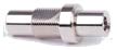
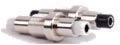
TC Manual RF Shield Box Custom I/O Interface Panel
Customized I/O Interface panels are available. Please contact the CTS sales team for more information
| I/O Interface | Order Number | Typical Data Rate/Line Voltage | Typical Shielding* |
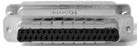
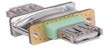
DB37, 1000pF pi Filter | 3409-0012-1 | 3 Mbps / 100 VDC,
5 Amps max | >70 dB from 0.5 to 2 GHz
>80 dB from 2 to 3 GHz
>70 dB from 3 to 6 GHz |
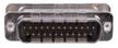
DB25, 1000pF pi Filter | 3409-0009-1 | 3 Mbps / 100 VDC,
5 Amps max | >70 dB from 0.5 to 2 GHz
>80 dB from 2 to 3 GHz
>70 dB from 3 to 6 GHz |
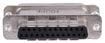
DB25, 100pF pi Filter | 3409-0014-1 | 10 Mbps / 100 VDC,
5 Amps max | >50 dB from 0.5 to 2 GHz
>60 dB from 2 to 3 GHz
>60 dB from 3 to 6 GHz |
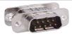
DB9, 1000pF pi Filter | 3409-0008-1 | 3 Mbps / 100 VDC,
5 Amps max | >70 dB from 0.5 to 2 GHz
>80 dB from 2 to 3 GHz
>70 dB from 3 to 6 GHz |
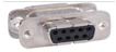
DB9, 100pF pi Filter | 3409-0010-1 | 10 Mbps / 100 VDC,
5 Amps max | >50 dB from 0.5 to 2 GHz
>60 dB from 2 to 3 GHz
>60 dB from 3 to 6 GHz |
USB 2.0 Filter | 3409-0018A-3 | 480 Mbps / 5 V, 500 mA /
Max Current: 5A | >60 dB from 0.5 to 2 GHz
>70 dB from 2 to 3 GHz
>70 dB from 3 to 6 GHz |
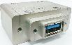
USB 3.0 Filter(Active) | 3409-0042A-1 | 5000 Mbps / 5 V, 900 mA /
Max Current: 1.5 A | >70 dB from 0.5 to 2 GHz
>70 dB from 2 to 3 GHz
>55 dB from 3 to 6 GHz |
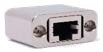
RJ-45 Filter | 3409-0022A | 1 Gbit/s Copper-Line
Ethernet (1000 BASE-T) | >60 dB from 0.5 to 2 GHz
>70 dB from 2 to 3 GHz
>70 dB from 3 to 6 GHz |
DC Power Adaptor | 3406-0004A | 50 VDC,
3 Amps max | >70 dB from 0.5 to 2 GHz
>80 dB from 2 to 3 GHz
>80 dB from 3 to 6 GHz |
DC Power Adaptor,
Banana Jack Type | 3406-0005A
3406-0006A | 50 VDC,
10 Amps max | >70 dB from 0.5 to 2 GHz
>80 dB from 2 to 3 GHz
>80 dB from 3 to 6 GHz |

AC Power Adaptor | 3103-0009A | 250 VAC,
7 Amps max | >70 dB from 0.5 to 2 GHz
>80 dB from 2 to 3 GHz
>80 dB from 3 to 6 GHz |
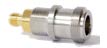
RF, N-SMA Connector | 3408-0038 | | >60 dB from 0.5 to 2 GHz
>70 dB from 2 to 3 GHz
>70 dB from 3 to 6 GHz |

RF, SMA-SMA Connector | 3408-0039 | | >60 dB from 0.5 to 2 GHz
>70 dB from 2 to 3 GHz
>70 dB from 3 to 6 GHz |
*SPECIFICATIONS SUBJECT TO CHANGE WITHOUT PRIOR NOTICE
- Each shielding effectiveness is measured when each I/O interface panel, which is shown above, is mounted.
- Above data was measured by Tescom, The Shielding Effectiveness might be different based on the measuring method and condition.
- This data has been measured under the condition that the cables are not connected to each filters. When the cables are connected it can affect the shielding performance.


