Description
TC-5915APU Pneumatic Shield Box – Key Benefits
-
Reliable high RF shielding for testing products up to 12 GHz with the upgraded “U” version
-
Pneumatic control for lid open/close and optional test fixture motion
-
Easily customizable to support a wide range of testing needs
-
Red and green LED indicators for clear pass/fail status
-
EMI filters on all data ports and the power line
-
Remote operation supported via RS-232C
High-Performance Pneumatic RF Shielding
The upgraded TC-5915APU Pneumatic Shield Box builds on the proven TC-5915AP design. The new “U” version extends RF shielding performance up to 12 GHz. As a result, it supports today’s higher-frequency wireless testing demands.
While it retains the trusted features engineers expect, this version delivers improved shielding performance. Consequently, it is well suited for modern wireless technology development and validation.
Optimized for OTA Testing
The TC-5915APU is designed specifically for over-the-air (OTA) testing. The interior walls are lined with highly absorbent RF absorber material. In addition, a ferrite absorber layer reinforces the design. Together, these materials significantly reduce internal reflections.
Because reflections can cause multipath issues, minimizing them is critical. This design creates a stable and controlled RF environment for accurate OTA measurements.
For a complete OTA testing setup, pair the shield box with a grid fixture and an antenna coupler. This combination improves repeatability and measurement reliability for handheld devices under test (DUTs).
Custom Test Fixture Options
If your application requires a tailored solution, custom test fixtures are also available. Our engineering team can design and integrate a fixture that matches your DUT requirements, budget, and schedule.
Understanding OTA Testing Performance
OTA testing requires precise placement of the DUT inside a shielded chamber. The shield box isolates the DUT from external interference. However, reflections and environmental noise can still impact results.
To address this, RF absorber material lines the interior of the TC-5915APU. This absorber works with the shield box to suppress reflections. As a result, the system delivers a clean and repeatable OTA test environment.
Solutions like this are engineered and supported by TESCOM to meet demanding wireless test requirements.
Specifications
Pneumatic RF Shield Box TC-5915APU Specifications
- Shielding Effectiveness : > from DC to 12GHz, with M591502B IO plate installed.
- Data line capacity : 100 VDC, 3 Amps max
- Remote control : RS-232C, 3 wire, DB9(p)
- Input air pressure : 5 bar to 10 bar
- Air Connections
- Main air connector : 6mm OD hose, one-touch push-on fitting
- Fixture control air connector : 4mm OD hose, one-touch push-on fitting
- Dimensions
- Inner Dimension : 220(W) x 280(D) x 170(H) mm
- Outer Dimension : 413(W) x 430(D) x 268(H) mm, lid closed; 372(H) mm, lid open
- Weight : approx. 9 kg
SPECIFICATIONS SUBJECT TO CHANGE WITHOUT PRIOR NOTICE
Typical RF Shielding
Typical RF Shielding
It is measured including the blank panel module, without cable. The shielding effectiveness can be different depend on the data connector in the module.
- 100 to 3000 MHz > 70 dB
- 3000 to 6000 MHz > 60 dB
- 6 to 12 GHz > 60 dB
***Isolation example above is based on I/O configuration as specified above. Isolation may be higher or lower based on specific I/O configuration installed.
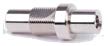
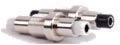
Custom Configurations
TC Manual RF Shield Box Custom I/O Interface Panel
Customized I/O Interface panels are available. Please contact the CTS sales team for more information
| I/O Interface | Order Number | Typical Data Rate/Line Voltage | Typical Shielding* |
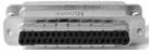
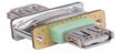
DB37, 1000pF pi Filter | 3409-0012-1 | 3 Mbps / 100 VDC,
5 Amps max | >70 dB from 0.5 to 2 GHz
>80 dB from 2 to 3 GHz
>70 dB from 3 to 6 GHz |
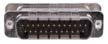
DB25, 1000pF pi Filter | 3409-0009-1 | 3 Mbps / 100 VDC,
5 Amps max | >70 dB from 0.5 to 2 GHz
>80 dB from 2 to 3 GHz
>70 dB from 3 to 6 GHz |
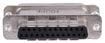
DB25, 100pF pi Filter | 3409-0014-1 | 10 Mbps / 100 VDC,
5 Amps max | >50 dB from 0.5 to 2 GHz
>60 dB from 2 to 3 GHz
>60 dB from 3 to 6 GHz |
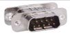
DB9, 1000pF pi Filter | 3409-0008-1 | 3 Mbps / 100 VDC,
5 Amps max | >70 dB from 0.5 to 2 GHz
>80 dB from 2 to 3 GHz
>70 dB from 3 to 6 GHz |
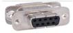
DB9, 100pF pi Filter | 3409-0010-1 | 10 Mbps / 100 VDC,
5 Amps max | >50 dB from 0.5 to 2 GHz
>60 dB from 2 to 3 GHz
>60 dB from 3 to 6 GHz |
USB 2.0 Filter | 3409-0018A-3 | 480 Mbps / 5 V, 500 mA /
Max Current: 5A | >60 dB from 0.5 to 2 GHz
>70 dB from 2 to 3 GHz
>70 dB from 3 to 6 GHz |
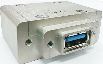
USB 3.0 Filter(Active) | 3409-0042A-1 | 5000 Mbps / 5 V, 900 mA /
Max Current: 1.5 A | >70 dB from 0.5 to 2 GHz
>70 dB from 2 to 3 GHz
>55 dB from 3 to 6 GHz |
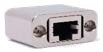
RJ-45 Filter | 3409-0022A | 1 Gbit/s Copper-Line
Ethernet (1000 BASE-T) | >60 dB from 0.5 to 2 GHz
>70 dB from 2 to 3 GHz
>70 dB from 3 to 6 GHz |
DC Power Adaptor | 3406-0004A | 50 VDC,
3 Amps max | >70 dB from 0.5 to 2 GHz
>80 dB from 2 to 3 GHz
>80 dB from 3 to 6 GHz |
DC Power Adaptor,
Banana Jack Type | 3406-0005A
3406-0006A | 50 VDC,
10 Amps max | >70 dB from 0.5 to 2 GHz
>80 dB from 2 to 3 GHz
>80 dB from 3 to 6 GHz |

AC Power Adaptor | 3103-0009A | 250 VAC,
7 Amps max | >70 dB from 0.5 to 2 GHz
>80 dB from 2 to 3 GHz
>80 dB from 3 to 6 GHz |
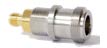
RF, N-SMA Connector | 3408-0038 | | >60 dB from 0.5 to 2 GHz
>70 dB from 2 to 3 GHz
>70 dB from 3 to 6 GHz |

RF, SMA-SMA Connector | 3408-0039 | | >60 dB from 0.5 to 2 GHz
>70 dB from 2 to 3 GHz
>70 dB from 3 to 6 GHz |
*SPECIFICATIONS SUBJECT TO CHANGE WITHOUT PRIOR NOTICE
- Each shielding effectiveness is measured when each I/O interface panel, which is shown above, is mounted.
- Above data was measured by Tescom, The Shielding Effectiveness might be different based on the measuring method and condition.
- This data has been measured under the condition that the cables are not connected to each filters. When the cables are connected it can affect the shielding performance.


