TC-5910DU RF Shield Box

SKU: TC-5910DU Categories: , ,

Description

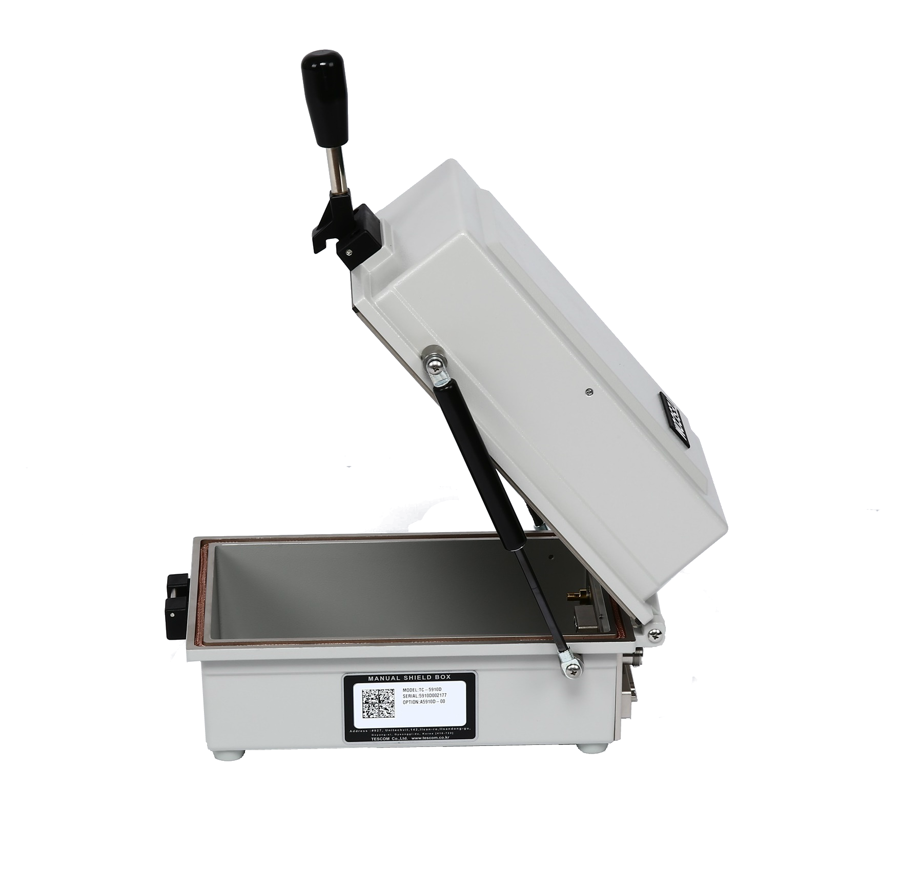
The TESCOM TC5910DU RF Shield Box is the upgraded version of the popular TC5910D. It delivers reliable RF shielding up to 12 GHz. As a result, it supports higher-frequency wireless testing requirements.

In addition, the TC5910DU retains the core features that engineers value in the TC5910D. However, it now offers improved shielding performance to meet modern wireless technology demands. Because of this upgrade, it works well for advanced RF and OTA testing applications.


Designed for Over-the-Air (OTA) Testing

The TC5910DU functions as a Faraday cage designed specifically for OTA testing. All interior walls include highly absorbent RF absorber material. Moreover, a layer of ferrite absorber helps reduce low-frequency reflections.

Because of this layered absorber design, the chamber minimizes reflections and multipath effects. Therefore, engineers can perform more accurate and repeatable OTA measurements. This controlled environment improves confidence in test results.


Flexible Test Configuration Options

To further enhance testing capability, users can add grid fixtures and antenna couplers. These accessories transform the TC5910DU into a complete OTA test solution. As a result, engineers can test handheld devices and other DUTs with consistent positioning.

Additionally, this flexible setup supports a wide range of device sizes and antenna types. Because of this adaptability, the shield box works well in both development labs and production environments.


How OTA Testing Is Performed

During OTA testing, engineers place the Device Under Test (DUT) inside the RF shield box. The chamber isolates the DUT from external RF interference. At the same time, the absorber-lined walls and antenna coupler reduce internal reflections.

The goal of OTA testing is to evaluate wireless performance in real-world conditions. However, many factors can affect results, including multipath reflections and outside interference. Because of these challenges, a controlled RF environment becomes essential.

By combining the TC5910DU RF Shield Box with an antenna coupler and fixture, engineers achieve better repeatability and measurement integrity. As a result, teams can validate device performance with greater confidence.

Additional information

Weight 5 kg
Dimensions 9.25 × 5.1 × 5.4 in
Function

Manual

Internal Depth

0-10in

Internal Height

0-6in

Internal Width

0-8in

Manufacturer

Tescom

Specifications

TC-5910DU Manual RF Shield Box Mechanical Specification

  • RF Shield Effectiveness: >70dB*
  • Inner Dimension: 142(W) x 243(L) x 134(H) mm
  • Outer Dimension: 207W) x 424(L) x 173(H) mm, lid closed. 435(H)mm, lid open
  • Weight without accessories: 7 kg
  • Supplied with Test Report and RF Cable, SS-402, N(m) to N(m) 1 m, 1 pc

*The shielding effectiveness is measured with blank panels installed; other I/O interface panels may result in different shielding effectiveness

Typical RF Shielding

TC-5910DU Manual RF Shield Box Typical RF Shielding

The shield effectiveness below is measured when the blank panel is mounted; other I/O interface panel results a different shielding effectiveness of the shield box.

  • 100 to 3 GHz > 70 dB
  • 3 to 6 GHz > 60 dB
  • 6 to 12 GHz > 60 dB

***Isolation example above is based on I/O configuration as specified above. Isolation may be higher or lower based on specific I/O configuration installed.

Custom Configurations

TC Manual RF Shield Box Custom I/O Interface Panel

Customized I/O Interface panels are available. Please contact the CTS sales team for more information

I/O InterfaceOrder NumberTypical Data Rate/Line VoltageTypical Shielding*

DB37, 1000pF pi Filter
3409-0012-13 Mbps / 100 VDC,
5 Amps max
>70 dB from 0.5 to 2 GHz
>80 dB from 2 to 3 GHz
>70 dB from 3 to 6 GHz

DB25, 1000pF pi Filter
3409-0009-13 Mbps / 100 VDC,
5 Amps max
>70 dB from 0.5 to 2 GHz
>80 dB from 2 to 3 GHz
>70 dB from 3 to 6 GHz

DB25, 100pF pi Filter
3409-0014-110 Mbps / 100 VDC,
5 Amps max
>50 dB from 0.5 to 2 GHz
>60 dB from 2 to 3 GHz
>60 dB from 3 to 6 GHz

DB9, 1000pF pi Filter
3409-0008-13 Mbps / 100 VDC,
5 Amps max
>70 dB from 0.5 to 2 GHz
>80 dB from 2 to 3 GHz
>70 dB from 3 to 6 GHz

DB9, 100pF pi Filter
3409-0010-110 Mbps / 100 VDC,
5 Amps max
>50 dB from 0.5 to 2 GHz
>60 dB from 2 to 3 GHz
>60 dB from 3 to 6 GHz

USB 2.0 Filter
3409-0018A-3480 Mbps / 5 V, 500 mA /
Max Current: 5A
>60 dB from 0.5 to 2 GHz
>70 dB from 2 to 3 GHz
>70 dB from 3 to 6 GHz

USB 3.0 Filter(Active)
3409-0042A-15000 Mbps / 5 V, 900 mA /
Max Current: 1.5 A
>70 dB from 0.5 to 2 GHz
>70 dB from 2 to 3 GHz
>55 dB from 3 to 6 GHz

RJ-45 Filter
3409-0022A1 Gbit/s Copper-Line
Ethernet (1000 BASE-T)
>60 dB from 0.5 to 2 GHz
>70 dB from 2 to 3 GHz
>70 dB from 3 to 6 GHz

DC Power Adaptor
3406-0004A50 VDC,
3 Amps max
>70 dB from 0.5 to 2 GHz
>80 dB from 2 to 3 GHz
>80 dB from 3 to 6 GHz

DC Power Adaptor,
Banana Jack Type
3406-0005A
3406-0006A
50 VDC,
10 Amps max
>70 dB from 0.5 to 2 GHz
>80 dB from 2 to 3 GHz
>80 dB from 3 to 6 GHz

AC Power Adaptor
3103-0009A250 VAC,
7 Amps max
>70 dB from 0.5 to 2 GHz
>80 dB from 2 to 3 GHz
>80 dB from 3 to 6 GHz

RF, N-SMA Connector
3408-0038>60 dB from 0.5 to 2 GHz
>70 dB from 2 to 3 GHz
>70 dB from 3 to 6 GHz

RF, SMA-SMA Connector
3408-0039>60 dB from 0.5 to 2 GHz
>70 dB from 2 to 3 GHz
>70 dB from 3 to 6 GHz

*SPECIFICATIONS SUBJECT TO CHANGE WITHOUT PRIOR NOTICE

  • Each shielding effectiveness is measured when each I/O interface panel, which is shown above, is mounted.
  • Above data was measured by Tescom, The Shielding Effectiveness might be different based on the measuring method and condition.
  • This data has been measured under the condition that the cables are not connected to each filters. When the cables are connected it can affect the shielding performance.