Description
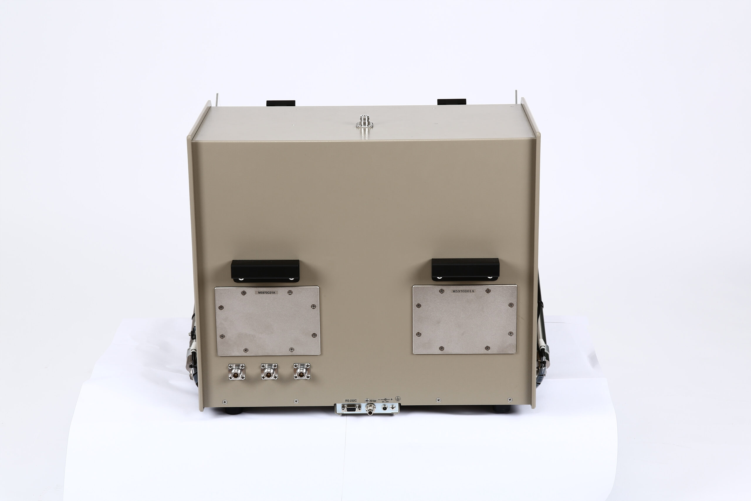
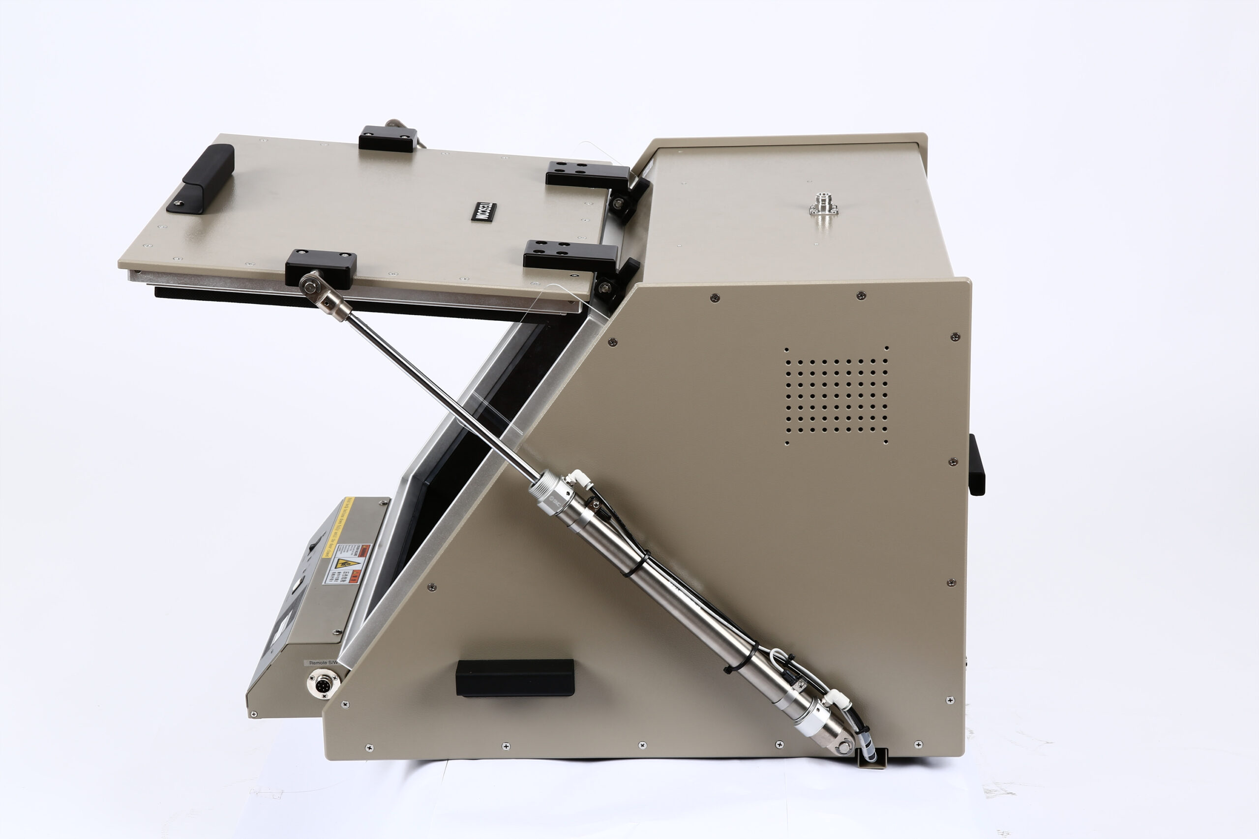
TC5972DP/CP RF Shield Box
- High RF shielding
- Easy Opening/Closing of Door
- 4 Standard RF Ports(N-Type Outside, SMA Inside) Built-In
- EMI filters on all Data and DC lines
- Installs up to Two Optional I/O Plates
- Easily Field Replaceable Rear I/O Connectors and I/O Plates
- Proprietary Multi-layer absorber for radiation testing
- Pneumatic control of lid open-close and optional test fixtures – Standard or Custom
- Shock Absorbers on Door
- Red and Green LED’s for Pass/Fail indication
- EMI filters on all data ports and power lines
- Remote operation by RS-232C
- Ferrite Absorber for radiation testing (TC-5972CP)
The TC5972DP RF Shield Box is the smaller pneumatic version of the TC5970D RF Shield Box. It provides both high RF isolation and room for testing Small to Medium size wireless devices. TC5972DP RF Shield Box is an ideal test platform for Engineering, Manufacturing, or service due to it’s size and ergonomic design. This RF Shield Box is built with durability and longevity for your testing now and for the future in a high volume environment as your testing requirements change as your products change. This is the last RF Shield Box you will need with all the various options for I/O plates and internal fixtures to accommodate your DUT(Device Under Test). With our proprietary multilayer RF absorber or the Ferrite absorber you will get consistent repeatable test results you can be confident of.
If you need the benefits of the pneumatically Operated TC-5972DP RF Shield Box but in a manual open/close shield box, you may want to consider the pneumatic TC-5972D RF Shield Box.
*SPECIFICATIONS SUBJECT TO CHANGE WITHOUT PRIOR NOTICE
Specifications
Mechanical Specifications
- RF Connectors without module: 4 N (f) outside and SMA (f) inside
- Line voltage: DC 24 V, Max. 2A.
- Remote control: RS-232C, 3 wire, DB9(s)
- Air connection
- Main Connector: 6 mm OD hose, one-touch push-on fitting
- Fixture Control Connector: 4 mm OD hose, one-touch push-on fitting
- Input Air Pressure: 5 to 10 bar
- Dimensions
- Inside: 470(W) x 470(D) x 360(H) mm, 230(D)mm top side
- Outside: 580(W)×661(D) ×452(H)mm
- Door: 420(W) x 358(H)
- Weight: approximately 48 kg
- Shielding effectiveness: >60dB DC~2.5GHz, >50dB 2.5~6GHz
- Data line Capacity: 100 VDC, 3 Amps maximum
- Inner walls lined with multi layer absorber: Inner Dimension: 445(W)×445(D) ×360(H)mm, 230(D)mm top side
Typical RF Shielding
The shield effectiveness below is measured when the blank panel is mounted; other I/O interface panel results a different shielding effectiveness of the shield box.
- 100 to 2000 MHz > 70 dB
- 2000 to 3000 MHz > 70 dB
- 3000 to 6000 MHz > 50 dB
***Isolation example above is based on I/O configuration as specified above. Isolation may be higher or lower based on specific I/O configuration installed.
Custom Configurations
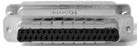
TC Manual RF Shield Box Custom I/O Interface Panel
Customized I/O Interface panels are available. Please contact the CTS sales team for more information
| I/O Interface | Order Number | Typical Data Rate/Line Voltage | Typical Shielding* |
DB37, 1000pF pi Filter | 3409-0012-1 | 3 Mbps / 100 VDC,
5 Amps max | >70 dB from 0.5 to 2 GHz
>80 dB from 2 to 3 GHz
>70 dB from 3 to 6 GHz |
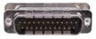
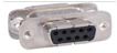
DB25, 1000pF pi Filter | 3409-0009-1 | 3 Mbps / 100 VDC,
5 Amps max | >70 dB from 0.5 to 2 GHz
>80 dB from 2 to 3 GHz
>70 dB from 3 to 6 GHz |
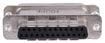
DB25, 100pF pi Filter | 3409-0014-1 | 10 Mbps / 100 VDC,
5 Amps max | >50 dB from 0.5 to 2 GHz
>60 dB from 2 to 3 GHz
>60 dB from 3 to 6 GHz |
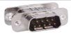
DB9, 1000pF pi Filter | 3409-0008-1 | 3 Mbps / 100 VDC,
5 Amps max | >70 dB from 0.5 to 2 GHz
>80 dB from 2 to 3 GHz
>70 dB from 3 to 6 GHz |
DB9, 100pF pi Filter | 3409-0010-1 | 10 Mbps / 100 VDC,
5 Amps max | >50 dB from 0.5 to 2 GHz
>60 dB from 2 to 3 GHz
>60 dB from 3 to 6 GHz |
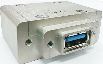
USB 2.0 Filter | 3409-0018A-3 | 480 Mbps / 5 V, 500 mA /
Max Current: 5A | >60 dB from 0.5 to 2 GHz
>70 dB from 2 to 3 GHz
>70 dB from 3 to 6 GHz |
USB 3.0 Filter(Active) | 3409-0042A-1 | 5000 Mbps / 5 V, 900 mA /
Max Current: 1.5 A | >70 dB from 0.5 to 2 GHz
>70 dB from 2 to 3 GHz
>55 dB from 3 to 6 GHz |
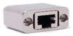
RJ-45 Filter | 3409-0022A | 1 Gbit/s Copper-Line
Ethernet (1000 BASE-T) | >60 dB from 0.5 to 2 GHz
>70 dB from 2 to 3 GHz
>70 dB from 3 to 6 GHz |
DC Power Adaptor | 3406-0004A | 50 VDC,
3 Amps max | >70 dB from 0.5 to 2 GHz
>80 dB from 2 to 3 GHz
>80 dB from 3 to 6 GHz |
DC Power Adaptor,
Banana Jack Type | 3406-0005A
3406-0006A | 50 VDC,
10 Amps max | >70 dB from 0.5 to 2 GHz
>80 dB from 2 to 3 GHz
>80 dB from 3 to 6 GHz |

AC Power Adaptor | 3103-0009A | 250 VAC,
7 Amps max | >70 dB from 0.5 to 2 GHz
>80 dB from 2 to 3 GHz
>80 dB from 3 to 6 GHz |
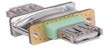
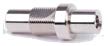
RF, N-SMA Connector | 3408-0038 | | >60 dB from 0.5 to 2 GHz
>70 dB from 2 to 3 GHz
>70 dB from 3 to 6 GHz |

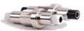
RF, SMA-SMA Connector | 3408-0039 | | >60 dB from 0.5 to 2 GHz
>70 dB from 2 to 3 GHz
>70 dB from 3 to 6 GHz |
*SPECIFICATIONS SUBJECT TO CHANGE WITHOUT PRIOR NOTICE
- Each shielding effectiveness is measured when each I/O interface panel, which is shown above, is mounted.
- Above data was measured by Tescom, The Shielding Effectiveness might be different based on the measuring method and condition.
- This data has been measured under the condition that the cables are not connected to each filters. When the cables are connected it can affect the shielding performance.