Description
The STE2902 RF Shielded Test Enclosure is designed for dense pack wireless test environments that require high RF isolation and efficient use of rack space. This enclosure system provides a controlled RF testing environment that supports accurate and repeatable validation of wireless devices in both lab and production settings.
Built for standard 19-inch rack mounting, the STE2902 RF Shielded Test Enclosure integrates two STE2900 WLAN test enclosures into a single 7 rack unit (12-inch high) package. This dual-enclosure design allows teams to increase test throughput without expanding their rack footprint.
Dual RF Shielded Enclosure Design for High-Density Testing
This RF shielded test enclosure system enables simultaneous testing of multiple devices while maintaining isolation between test chambers. By preventing devices from communicating with each other or the outside world, the STE2902 RF Shielded Test Enclosure supports reliable evaluation of Wi-Fi, Bluetooth, and other wireless technologies in high-density environments.
Rack-Mount Configuration and Accessibility
An integrated custom rack shelf provides secure mounting and support for use in standard 19-inch racks. Front-loading doors swing away to the left, allowing easy access to devices under test and simplifying installation, removal, and servicing. This design improves workflow efficiency in both engineering labs and manufacturing lines.
Thermal Performance and Mobility Options
The enclosure supports proper airflow and thermal stability, allowing devices to operate within published specifications during extended test cycles. For mobile or field testing applications, the STE2902 RF Shielded Test Enclosure is also available in a shock-mounted road case for safe transport, fast setup, and repeatable performance at remote locations.
Typical Applications
-
Dense wireless device testing
-
Manufacturing and production validation
-
Multi-DUT RF performance testing
-
Lab and mobile RF test environments
IO Configurations
Custom Configuration Options
- RF FEEDTHROUGH: BNC, TNC, SMA, SMB, UHF, Type-N
- FIBER OPTIC: Fiber optic bulkhead feedthrough, ST, FC
- DUST COVERS: Dust cover capes with security chains available for all RF feedthrough connectors
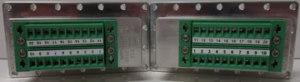
- RF FILTERED DATA: DB9 (10pF), DB9 (100pF), DB9 (1000pF), DB15 (100pF), DB15 (1000pF), DB25 (310pF), DB25 (1000pF), DB37 (310pF), DB37 (1000pF), RJ45/DB9 Filtered, RJ11/DB9 Filtered, USB1/DB9 Filtered
- POWER CONNECTIONS: 4-Pole filtered barrier strip feed through, 6-Pole filtered barrier strip feed through, internal surge protected power strips (110VAC, 220VAC International)
- VENTILATION OPTIONS: Dual side mounted RF filtered vents with single filtered exhaust muffin fan, passive vent only
- RF ABSORBENT FOAM: Standard 1/2″ thick RF absorbent foram liner provides 24dB attenuation. 3/4″ thick foam is standard on the STE3800 and available as an option to provide a flatter response
- FIBER TRANSCEIVER: Icron Technologies USB 2.0 Fiber Transceiver System available for devices up to 480 MB/s
Note: RF Isolation specs are measured at 1M with terminated RF feedthrough coaxial connectors installed. Actual isolation & attenuation can be affected by adding additional filtered and non-filtered connectors. Check with us for specific connector specifications. STE series I/O interfaces, connectors, and options are frequently updated. Check with us for updates.
| I/O Interface | Order Number | Typical Data Rate/Line Voltage | Typical Shielding* |
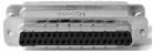
DB37, 1000pF pi Filter | 3409-0012-1 | 3 Mbps / 100 VDC,
5 Amps max | >70 dB from 0.5 to 2 GHz
>80 dB from 2 to 3 GHz
>70 dB from 3 to 6 GHz |
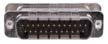
DB25, 1000pF pi Filter | 3409-0009-1 | 3 Mbps / 100 VDC,
5 Amps max | >70 dB from 0.5 to 2 GHz
>80 dB from 2 to 3 GHz
>70 dB from 3 to 6 GHz |
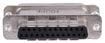
DB25, 100pF pi Filter | 3409-0014-1 | 10 Mbps / 100 VDC,
5 Amps max | >50 dB from 0.5 to 2 GHz
>60 dB from 2 to 3 GHz
>60 dB from 3 to 6 GHz |
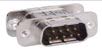
DB9, 1000pF pi Filter | 3409-0008-1 | 3 Mbps / 100 VDC,
5 Amps max | >70 dB from 0.5 to 2 GHz
>80 dB from 2 to 3 GHz
>70 dB from 3 to 6 GHz |
DB9, 100pF pi Filter | 3409-0010-1 | 10 Mbps / 100 VDC,
5 Amps max | >50 dB from 0.5 to 2 GHz
>60 dB from 2 to 3 GHz
>60 dB from 3 to 6 GHz |
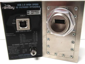 | STEUSB2071 |
Max Current: 2A | >80 dB from 741MHz to 6 GHz |
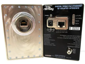 | STEETHD10G | 10 Gbps | >80dB 100MHz to 40GHz |
 | STEUSB3CC | Max Current 3.75A | >90 DB 200MHz to 8 GHz |
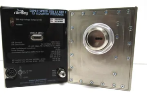
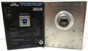 | STEUSB312 | Max Current: 2A | >90 DB 200MHz to 8 GHz |
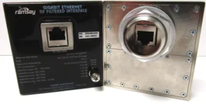 | STEGBE4591 | 1 GBps | >90 DB 700MHz to 8 GHz |
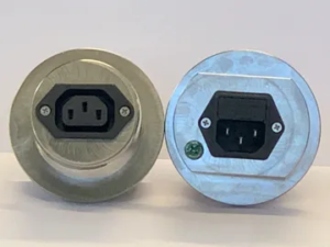 | IEC25010C | 250 VAC 10A | >80 dB at 200 MHz to 30 GHz |
 | STEDC2010 | 100 VDC 10A, 48VAC, 10 A | >90 dB 1GHz to 3 GHz |


