Description
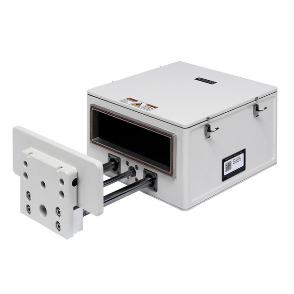
The TC-5924AP Pneumatic RF Shield Box is built for high-volume automated RF testing. It delivers fast cycle times, consistent performance, and strong RF isolation. As a result, manufacturers can improve throughput without sacrificing accuracy.
Unlike manual enclosures, the pneumatic lid system allows quick and repeatable opening and closing. Therefore, operators reduce handling time and fatigue. In addition, the guided pneumatic action ensures even pressure on the RF gasket every time. This helps maintain stable shielding over long production runs.
Strong RF Isolation for Wireless Testing
The TC-5924AP Pneumatic RF Shield Box creates a controlled test environment. Because it blocks outside interference, engineers can capture clean and repeatable measurements.
It supports testing for:
Furthermore, filtered I/O ports allow power and signal lines to pass through the enclosure without reducing shielding performance. Optional RF coupling antennas also support conducted and OTA testing. As a result, the system adapts easily to different test setups.
Designed for Production and R&D
The TC-5924AP fits smoothly into automated test systems. For example, it can be used on production lines, in engineering labs, or at quality control stations.
It is ideal for:
Because of its rugged build, the enclosure performs reliably under repeated daily use. In addition, its industrial components support long service life in high-cycle environments.
Flexible and Reliable Performance
Whether used on a benchtop or integrated into a full automation system, the TC-5924AP Pneumatic RF Shield Box delivers consistent results. Moreover, its modular port layout allows customization based on your test needs. This flexibility makes it easier to support new wireless standards as they evolve.
Overall, the TC-5924AP offers a practical solution for engineers who need speed, repeatability, and dependable RF isolation in modern test environments.
Typical RF Shielding
TC-5924AP Pneumatic Shield Box Typical RF Shielding
The shielding effectiveness below is measured when the blank panel is mounted; other I/O interface panel results a different shielding effectiveness of the shield box.
| Frequency |
Shielding effectiveness (dB) |
| 100 to 2000 MHz |
> 80 dB |
| 2000 to 3000 MHz |
> 80 dB |
| 3000 to 6000 MHz |
> 70 dB |
- Each shielding effectiveness is measured when each I/O interface panel, which is shown above, is mounted.
- Above data was measured by Tescom, The Shielding Effectiveness might be different based on the measuring method and condition.
- This data has been measured under the condition that the cables are not connected to each filters. When the cables are connected it can affect the shielding performance.
Custom Configurations
TC Manual RF Shield Box Custom I/O Interface Panel
Customized I/O Interface panels are available. Please contact the CTS sales team for more information
| I/O Interface | Order Number | Typical Data Rate/Line Voltage | Typical Shielding* |
DB37, 1000pF pi Filter | 3409-0012-1 | 3 Mbps / 100 VDC,
5 Amps max | >70 dB from 0.5 to 2 GHz
>80 dB from 2 to 3 GHz
>70 dB from 3 to 6 GHz |
DB25, 1000pF pi Filter | 3409-0009-1 | 3 Mbps / 100 VDC,
5 Amps max | >70 dB from 0.5 to 2 GHz
>80 dB from 2 to 3 GHz
>70 dB from 3 to 6 GHz |
DB25, 100pF pi Filter | 3409-0014-1 | 10 Mbps / 100 VDC,
5 Amps max | >50 dB from 0.5 to 2 GHz
>60 dB from 2 to 3 GHz
>60 dB from 3 to 6 GHz |
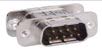
DB9, 1000pF pi Filter | 3409-0008-1 | 3 Mbps / 100 VDC,
5 Amps max | >70 dB from 0.5 to 2 GHz
>80 dB from 2 to 3 GHz
>70 dB from 3 to 6 GHz |
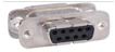
DB9, 100pF pi Filter | 3409-0010-1 | 10 Mbps / 100 VDC,
5 Amps max | >50 dB from 0.5 to 2 GHz
>60 dB from 2 to 3 GHz
>60 dB from 3 to 6 GHz |
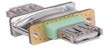
USB 2.0 Filter | 3409-0018A-3 | 480 Mbps / 5 V, 500 mA /
Max Current: 5A | >60 dB from 0.5 to 2 GHz
>70 dB from 2 to 3 GHz
>70 dB from 3 to 6 GHz |
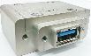
USB 3.0 Filter(Active) | 3409-0042A-1 | 5000 Mbps / 5 V, 900 mA /
Max Current: 1.5 A | >70 dB from 0.5 to 2 GHz
>70 dB from 2 to 3 GHz
>55 dB from 3 to 6 GHz |
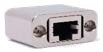
RJ-45 Filter | 3409-0022A | 1 Gbit/s Copper-Line
Ethernet (1000 BASE-T) | >60 dB from 0.5 to 2 GHz
>70 dB from 2 to 3 GHz
>70 dB from 3 to 6 GHz |
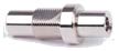
DC Power Adaptor | 3406-0004A | 50 VDC,
3 Amps max | >70 dB from 0.5 to 2 GHz
>80 dB from 2 to 3 GHz
>80 dB from 3 to 6 GHz |
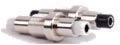
DC Power Adaptor,
Banana Jack Type | 3406-0005A
3406-0006A | 50 VDC,
10 Amps max | >70 dB from 0.5 to 2 GHz
>80 dB from 2 to 3 GHz
>80 dB from 3 to 6 GHz |

AC Power Adaptor | 3103-0009A | 250 VAC,
7 Amps max | >70 dB from 0.5 to 2 GHz
>80 dB from 2 to 3 GHz
>80 dB from 3 to 6 GHz |
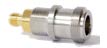
RF, N-SMA Connector | 3408-0038 | | >60 dB from 0.5 to 2 GHz
>70 dB from 2 to 3 GHz
>70 dB from 3 to 6 GHz |

RF, SMA-SMA Connector | 3408-0039 | | >60 dB from 0.5 to 2 GHz
>70 dB from 2 to 3 GHz
>70 dB from 3 to 6 GHz |
*SPECIFICATIONS SUBJECT TO CHANGE WITHOUT PRIOR NOTICE
- Each shielding effectiveness is measured when each I/O interface panel, which is shown above, is mounted.
- Above data was measured by Tescom, The Shielding Effectiveness might be different based on the measuring method and condition.
- This data has been measured under the condition that the cables are not connected to each filters. When the cables are connected it can affect the shielding performance.