Description
To allow proper cooling of the DUT each STE2950 includes a built-in passive 60mm vent option. Optional forced-air fans can be ordered for additional cooling. Like other Ramsey enclosures, our universal I/O panel on the back wall is included and ready for your custom configuration to meet your application. Heavy duty, rugged .090 and .125 aluminum is used throughout and our double lip, high performance gaskets are used at all joint locations assuring a reliable RF tight closure. RF absorbent foam lines the interior to provide a typical RF attenuation of -90dB @ 3GHz. If you are looking for an off-the-shelf RF enclosure system providing enough room to test any size wireless device, from Cellular phones to MIMO access points, you can count on the STE2950 to keep the device isolated.
The STE2952 includes dual STE2950’s mounted on a custom 19″ rack mount slide ready for installation into your rack. Access to the DUT is easy by the pull-out slide giving you full access to the hinged top mounted shielded doors. If you don’t have available rack space or need high density testing in the field, our STE2952C has dual STE2950’s pre-mounted and configured in a custom shock mounted road case. Great for field service trips.
RF Shield Box STE2950 Key Benefits
- Wireless device testing.
- Forensics Isolation
- Perfect for 802.11a, b, g, n, WiMAX
- Cellular, PCS, GSM, 3G testing
- 802.15, Bluetooth, Wibree, RFID, ZigBee testing
- Wide variety of I/O options are “standard”.
- Super isolation up to 18 GHz.
- RF radiating test fixture models for absolute repeatability testing of wireless devices.
- Stock models to fit your custom applications!
SPECIFICATIONS SUBJECT TO CHANGE WITHOUT PRIOR NOTICE
IO Configurations
Custom Configuration Options
- RF FEEDTHROUGH: BNC, TNC, SMA, SMB, UHF, Type-N
- FIBER OPTIC: Fiber optic bulkhead feedthrough, ST, FC
- DUST COVERS: Dust cover capes with security chains available for all RF feedthrough connectors
- RF FILTERED DATA: DB9 (10pF), DB9 (100pF), DB9 (1000pF), DB15 (100pF), DB15 (1000pF), DB25 (310pF), DB25 (1000pF), DB37 (310pF), DB37 (1000pF), RJ45/DB9 Filtered, RJ11/DB9 Filtered, USB1/DB9 Filtered
- POWER CONNECTIONS: 4-Pole filtered barrier strip feed through, 6-Pole filtered barrier strip feed through, internal surge protected power strips (110VAC, 220VAC International)
- VENTILATION OPTIONS: Dual side mounted RF filtered vents with single filtered exhaust muffin fan, passive vent only
- RF ABSORBENT FOAM: Standard 1/2″ thick RF absorbent foram liner provides 24dB attenuation. 3/4″ thick foam is standard on the STE3800 and available as an option to provide a flatter response
- FIBER TRANSCEIVER: Icron Technologies USB 2.0 Fiber Transceiver System available for devices up to 480 MB/s
Note: RF Isolation specs are measured at 1M with terminated RF feedthrough coaxial connectors installed. Actual isolation & attenuation can be affected by adding additional filtered and non-filtered connectors. Check with us for specific connector specifications. STE series I/O interfaces, connectors, and options are frequently updated. Check with us for updates.
| I/O Interface | Order Number | Typical Data Rate/Line Voltage | Typical Shielding* |

DB37, 1000pF pi Filter | 3409-0012-1 | 3 Mbps / 100 VDC,
5 Amps max | >70 dB from 0.5 to 2 GHz
>80 dB from 2 to 3 GHz
>70 dB from 3 to 6 GHz |

DB25, 1000pF pi Filter | 3409-0009-1 | 3 Mbps / 100 VDC,
5 Amps max | >70 dB from 0.5 to 2 GHz
>80 dB from 2 to 3 GHz
>70 dB from 3 to 6 GHz |

DB25, 100pF pi Filter | 3409-0014-1 | 10 Mbps / 100 VDC,
5 Amps max | >50 dB from 0.5 to 2 GHz
>60 dB from 2 to 3 GHz
>60 dB from 3 to 6 GHz |

DB9, 1000pF pi Filter | 3409-0008-1 | 3 Mbps / 100 VDC,
5 Amps max | >70 dB from 0.5 to 2 GHz
>80 dB from 2 to 3 GHz
>70 dB from 3 to 6 GHz |

DB9, 100pF pi Filter | 3409-0010-1 | 10 Mbps / 100 VDC,
5 Amps max | >50 dB from 0.5 to 2 GHz
>60 dB from 2 to 3 GHz
>60 dB from 3 to 6 GHz |
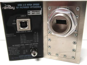 | STEUSB2071 |
Max Current: 2A | >80 dB from 741MHz to 6 GHz |
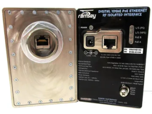 | STEETHD10G | 10 Gbps | >80dB 100MHz to 40GHz |
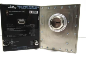 | STEUSB3CC | Max Current 3.75A | >90 DB 200MHz to 8 GHz |
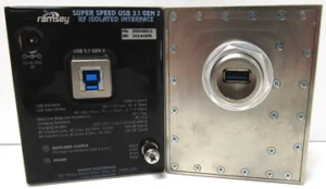 | STEUSB312 | Max Current: 2A | >90 DB 200MHz to 8 GHz |
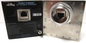 | STEGBE4591 | 1 GBps | >90 DB 700MHz to 8 GHz |
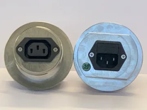 | IEC25010C | 250 VAC 10A | >80 dB at 200 MHz to 30 GHz |
 | STEDC2010 | 100 VDC 10A, 48VAC, 10 A | >90 dB 1GHz to 3 GHz |


